
Fluid Flow Technology That Measures Up
Originating Technology/ NASA Contribution
From 1994 to 1996, NASA’s Marshall Space Flight Center conducted a Center Director’s Discretionary Fund research effort to apply artificial intelligence technologies to the health management of plant equipment and space propulsion systems. Through this effort, NASA established a business relationship with Quality Monitoring and Control (QMC), of Kingwood, Texas, to provide hardware modeling and artificial intelligence tools. Very detailed and accurate Space Shuttle Main Engine (SSME) analysis and algorithms were jointly created, which identified several missing, critical instrumentation needs for adequately evaluating the engine health status. One of the missing instruments was a liquid oxygen (LOX) flow measurement. This instrument was missing since the original SSME included a LOX turbine flow meter that failed during a ground test, resulting in considerable damage for NASA. New balanced flow meter technology addresses this need with robust, safe, and accurate flow metering hardware.
Marshall and QMC engineers performed extensive modeling and analysis of the SSME system, and determined that the existing instrumentation was not sufficient to fully evaluate the SSME health status primarily relating to turbine blade failures. With existing instruments, the best system models have approximately 2.5-percent error and actual data show that very significant hardware failures produce an efficiency change of less than 1 percent, which is within the error band, making many failures impossible to detect. The need for a direct LOX measurement with less than 1-percent error was clear, but the way to do it was not, since the SSME hardware and environmental requirements are extreme. To meet the SSME LOX flow need, the group required a meter that would operate in different fluid physical states; accommodate wide variations in temperature, pressure, vibration, and flow conditions; measure flow with less than 1-percent error; and provide a mechanically robust system with low probability of failure. In addition to these strict requirements, other desired features included operation in different fluid mediums (liquid hydrogen, liquid oxygen, kerosene, etc.); operation in any gravity environment; simplified, long-lasting meter calibration; minimal intrusion into the flow path; and the ability to measure, condition, or limit flow within the same design.
With all of these requirements in mind, the balanced flow meter technology was conceived, created, and tested through the Marshall Technology Investment Projects program. The combination of unique hardware design and unique algorithms met all of the objectives in laboratory experimentation. Testing to harsher environments, in different fluids, and in bi-phase situations is continuing.
Partnership
Based upon its work with NASA, QMC founded A+FlowTek, also of Kingwood, Texas, to commercialize the balanced flow meter technology. Together, A+FlowTek and NASA patented the Balanced Flow Meter, with the company receiving exclusive licensing rights.
Product Outcome
The Balanced Flow Meter determines the fluid flow rate in piping, channel, and conduit systems. It provides highly accurate flow metering, flow limiting, or flow conditioning in any fluid flow system. As a flow meter, the technology provides flow measurement with minimal intrusion into the flow path and requires no moving parts. Additionally, this technology is LOX-safe and the hardware is robust enough for consideration as an engine LOX flow meter. As a flow limiting device, the technology can simulate facility and engine fluid flow loads. The technology’s sizing is more accurate than the currently used orifice plate technology, and it takes much less space and cost compared to Venturi flow technology. Finally, as a flow conditioning device, the balanced flow technology may improve engine performance by conditioning fluid flow profiles around elbows, combustion chambers, and pump inlets.
Fluid flow measurements such as these are used extensively in the processing industries for refineries and chemical, power, and pharmaceutical plants. Chevron and Sloss Industries are among the companies already using the Balanced Flow Meter technology in their industrial plants with good results.
The Balanced Flow Meter’s applications to NASA’s liquid propulsion systems and test facilities are numerous. Possible near-term NASA applications include using the technology as a flow limit device to simulate the engine loads during Stennis Space Center facility verifications. Once the concept is proven in the appropriate environments, there could be thousands of NASA applications for this promising technology.
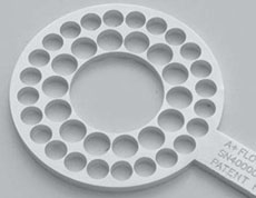
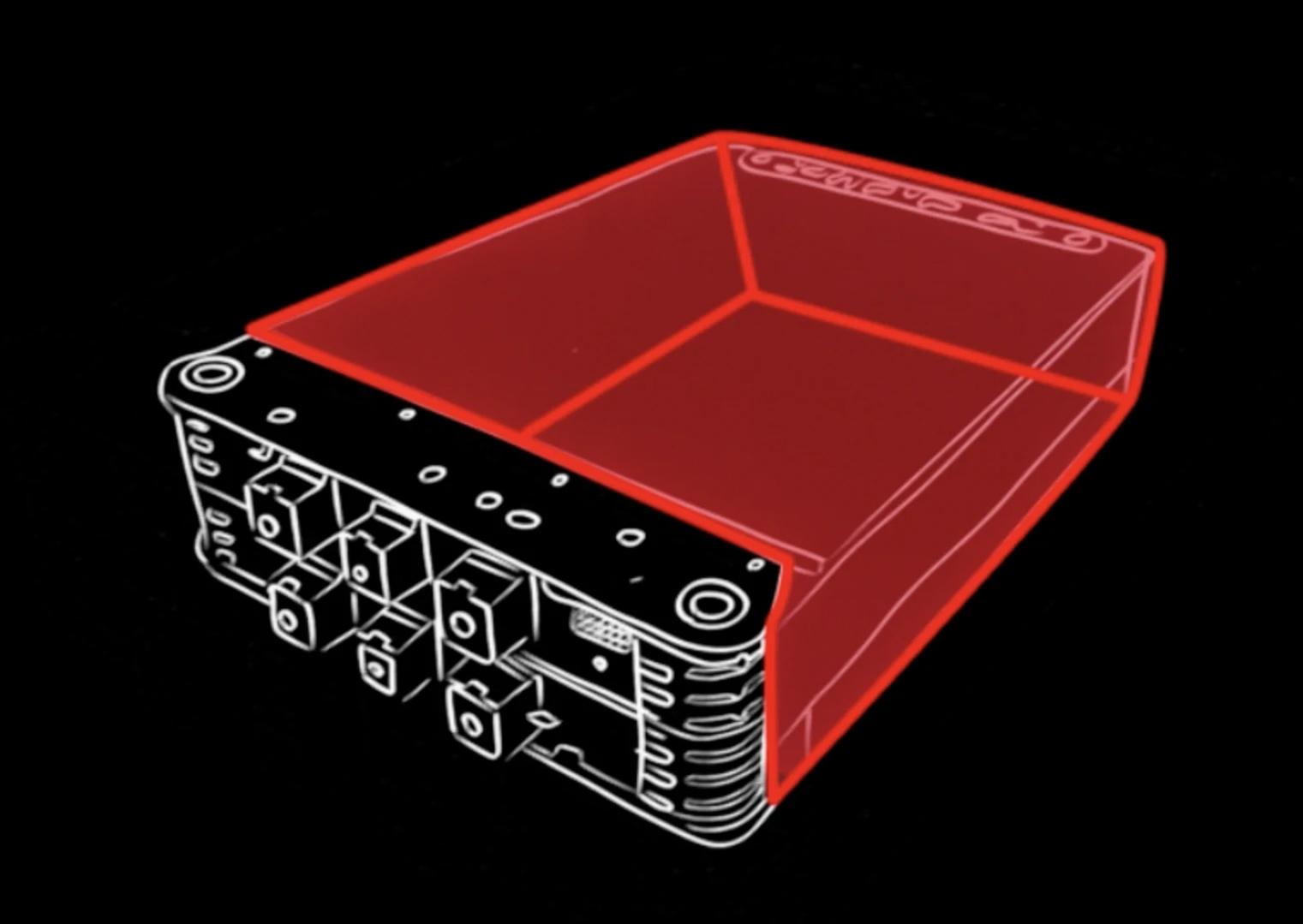
7.5-inch Kerosene Rocket Engine Flow Plate with an 81-percent open area.